Stamped Sheet Metal AI Defect Detection: Splits, Wrinkles, and Surface Defects on Body Panels

Stamping is one of the oldest, fastest, and least forgiving processes in automotive manufacturing. A single press cycle takes a flat steel or aluminum blank and forms it into a door, hood, fender, or structural component in a few seconds. The process is also defect-prone in highly specific ways. Splits at high-strain regions. Wrinkles in deep-drawn areas. Scratches from die wear. Springback dimensional drift over a tooling lifecycle.
Inspection is hard for the same reason the process is fast: the parts are large, reflective, and dimensionally complex. Manual end-of-line inspection catches the obvious failures but routinely misses subtle defects that fail at the body shop or, worse, after the vehicle ships. AI vision solves the consistency problem at line speed (240 parts per minute typical) without slowing the press.
This post is a working defect catalog for stamped sheet metal AI inspection, with detection approaches per defect class and deployment guidance for body panel programs.
The defect catalog
Splits and tears
Caused by material thinning beyond the forming limit, typically at deep-drawn corners, sharp radii, or material grain transitions. Splits are the most safety-critical stamping defect and the easiest to under-detect at line speed. The visible split width is often under 0.5mm.
Detection approach: high-resolution imaging at 50 to 100 µm pixel size combined with a CNN trained on split geometry. Recent research using ResNet18 architectures achieves 99.9 percent classification accuracy on split defects in stamped components. Production deployments routinely match this in real-time inference.
Wrinkles
Compressive instability in deep-drawn regions, typically along blank-holder transitions or at flange edges. Cosmetic wrinkles on Class A surfaces fail customer inspection. Functional wrinkles in load-path regions compromise crash performance.
Detection approach: photometric stereo to extract surface normal maps, with a classifier trained on wrinkle topology. See our coverage of photometric AI vision for edge defects in stamping for the full lighting architecture.
Scratches and die marks
Caused by die wear, contamination on tooling surfaces, or material handling damage. Scratches deeper than 0.1mm on Class A surfaces require rework or scrap. Detection approach: structured lighting plus an AI classifier trained per scratch direction (with-grain vs cross-grain produce different visual signatures).
Dents and surface waviness
Localized depressions or undulations from press tooling, transfer system contact, or operator handling. Particularly visible on dark paint colors and metallic finishes after paint application. Detection approach: 3D imaging or photometric stereo, with depth-aware classifier and location-specific tolerance bands.
Springback and dimensional drift
Material elastic recovery causes dimensional shift after the part leaves the die. Springback is process-inherent; dimensional drift over time as the die wears is the inspection challenge. Detection approach: 2D AI vision is insufficient; pair with structured-light or laser triangulation for measurement-grade dimensional inspection. The AI vision system handles defect detection while the metrology system tracks dimensional drift.
Edge defects: burrs, neck defects, fractured edges
Trim and pierce operations produce burrs and edge fractures that compromise downstream assembly. Neck defects (localized thinning at edge corners) are particularly hard to spot at line speed. Detection approach: edge-tangent imaging with high pixel density along part perimeters, classifier trained on the specific edge defect taxonomy of your tooling.
Hole and trim feature defects
Pierced holes that are out of position, undersized, or have torn edges from a worn punch. Trim features that don't meet contour. Detection approach: feature localization classifier plus dimensional measurement against the CAD model.
Why reflective surfaces are the hard part
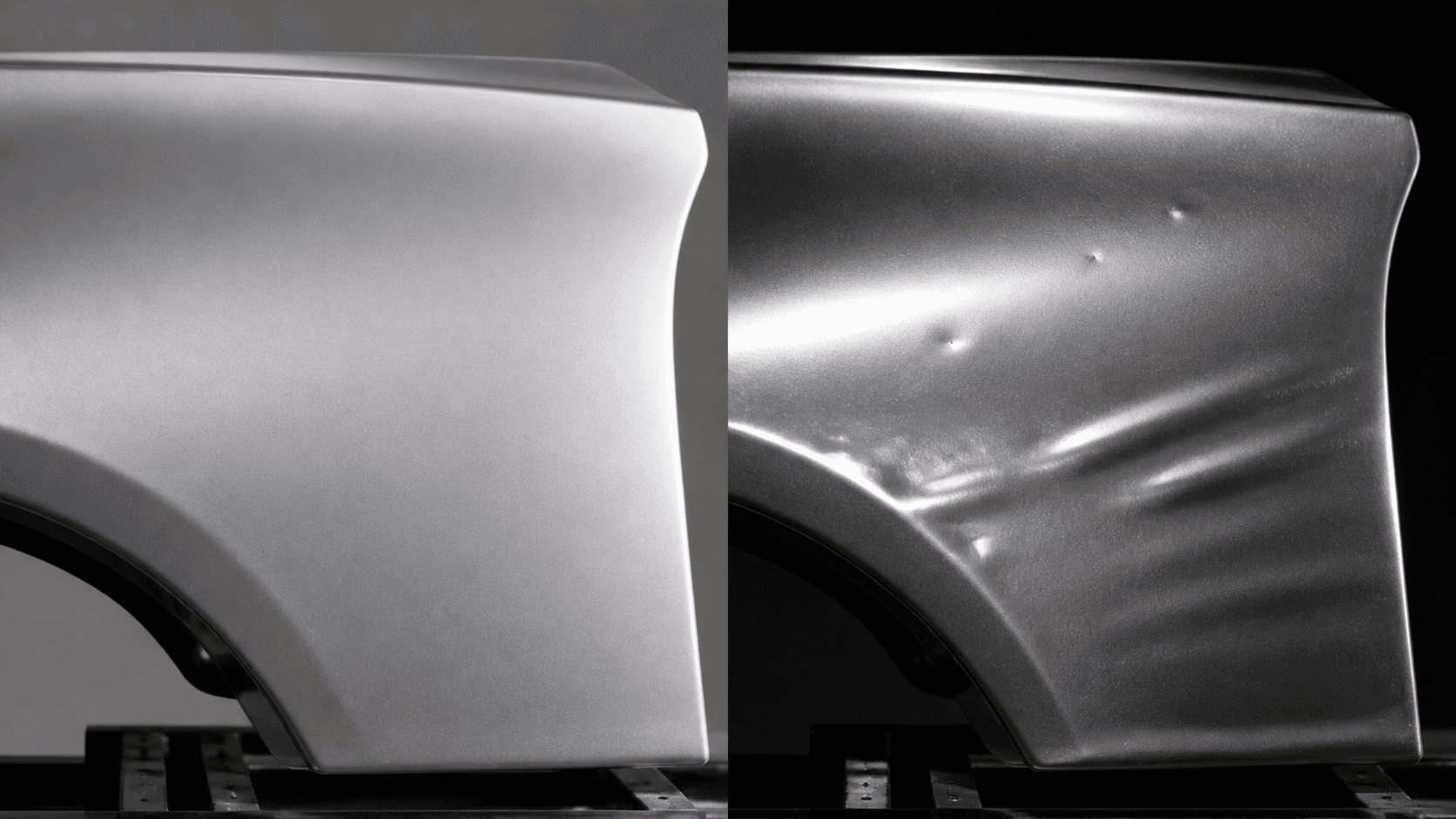
Body panels are designed to be reflective. That is exactly what makes them hard to inspect. A 1mm dent on a Class A surface is invisible under flat illumination but obvious under raking light. The lighting architecture, not the AI model, is what determines whether you catch the defect.
Three lighting strategies dominate stamped panel inspection:
Photometric stereo. Multiple lighting positions, single camera. Reconstructs a surface-normal map from differential illumination. Best for dents, wrinkles, and surface waviness on highly reflective surfaces. Lighting hardware is moderately complex but the inspection station footprint stays compact.
Structured-light triangulation. Projected pattern, multi-angle imaging. Reconstructs full 3D geometry. Best when you need both defect detection AND dimensional measurement at the same station. Slower and more expensive than photometric stereo.
Polarized lighting. Cross-polarized illumination cancels surface glare and exposes substrate defects. Best for paint-line inspection where surface reflections dominate but somewhat redundant for raw stamping inspection.
For a typical body panel program, photometric stereo is the right starting point. Structured-light is added selectively for parts where dimensional measurement matters at the same station as defect detection.
Where to put inspection in the stamping line
Three inspection points yield meaningful detection-rate-per-camera economics:
Between forming stages. For multi-stage operations (deep draw, restrike, trim, pierce), inspection between stages catches splits and wrinkles before secondary operations lock them in. Saves rework downstream.
Post-trim, before transfer. Most common deployment point. Stable thermal environment, multiple lighting angles possible, full part visibility achievable.
Final dimensional check after springback. Springback continues for several seconds after die release. End-of-line dimensional inspection captures the final part geometry that downstream operations actually receive.
Production data and economics
Industrial AI vision systems on stamping lines target:
- Cycle time: 240 parts per minute capability (sub-100ms inference)
- Resolution: 50 to 100 µm pixel size for split detection
- False reject rate: 1 to 3 percent on tuned production lines
- Critical defect escape rate: Below 50 PPM on splits and structural defects
- Surface defect detection: 0.2mm anomaly visibility at 98.7 percent accuracy on tuned systems
For a typical Tier-1 stamping operation running 8 million parts per year per line at $40 per part, a 30 percent reduction in escape rate to the body shop saves roughly $80,000 to $200,000 per year per line in rework and scrap, depending on the part program.
Why training data is easier than expected
The Open Stamped Parts Dataset and similar industry datasets provide thousands of pre-labeled stamped images that bootstrap initial training. Real production data is then collected during a 1 to 2 week onboarding window per defect class. For rare defects (less than 1 per 10,000 parts), synthetic defect generation closes the gap.
Stamped sheet metal is a particularly good fit for synthetic data augmentation because the defect classes are visually consistent across part programs. A split is a split, whether it appears on a Toyota Camry door or a Ford F-150 fender. Defect physics carry over even when visual context (paint color, surface texture, material gauge) varies.
Getting started
For more on the broader automotive AI vision deployment shape, see how AI vision reduces automotive defects and the Automotive Industry page.
Inspecting stamped body panels?
Send us images of your hardest defect class on the part program you care about. We will train a model in 1 to 3 hours and benchmark detection rate against your current inspection process.
Request a Stamping PilotFrequently Asked Questions
What defects affect stamped sheet metal parts?
The major defect classes are splits and tears at high-strain regions, wrinkles in deep-drawn areas, scratches from die wear or material handling, dents from press tooling or transfer, surface waviness, springback dimensional drift, and edge defects such as burrs, neck defects, and fractured edges. Each class has distinct visual characteristics and root causes.
Can AI vision detect splits in stamped parts at line speed?
Yes. Production AI vision systems detect splits with 99 percent or better accuracy at automotive line speeds of around 240 parts per minute. Recent published research using ResNet18 reports 99.9 percent classification accuracy on split defects in stamped components, and modern industrial deployments meet or exceed this threshold.
How does AI vision handle reflective surfaces on body panels?
Reflective surfaces require structured lighting, polarization filters, or photometric stereo to extract surface defects from glare. AI classifiers trained on the resulting normal maps reliably distinguish defects from acceptable surface variation. On highly reflective parts the lighting design matters more than the algorithm choice.
Where in the stamping line should inspection happen?
Three inspection points yield the best detection economics: between forming stages to catch splits before secondary operations lock them in, post-trim before transfer to the body shop, and a final dimensional check after springback has stabilized. Most lines start with end-of-line inspection and add upstream stations as the program matures.
See how Overview AI inspects stamped sheet metal defects
Send us a photo of your part or defect and a vision engineer will tell you whether Overview can catch it, with most systems deployed on the line in days.
Related Articles
Photometric AI Vision for Edge Defect Detection in Metal Stamping
Detect micro-fractures and burrs on reflective stamped parts by eliminating glare with adaptive illumination.
Read More →Steel Strip Surface Defect Detection with AI Vision
Detect scratches, pits, edge cracks, and surface defects on steel strips with AI vision at production line speed.
Read More →AI Bolt and Fastener Inspection on Reflective Surfaces
Detect loose and missing fasteners on oily, reflective assemblies using segmentation and glare-robust optics.
Read More →