Lithium Battery Pouch Cell Defect Inspection: A Defect Catalog

Pouch cells are the most inspection-difficult of the three lithium battery formats. Where prismatic and cylindrical cells present a single dominant inspection surface, pouch cells expose six. Where prismatic cans absorb light predictably, the aluminum-laminated foil on a pouch cell is highly reflective and changes appearance with every degree of viewing angle. Where cylindrical cells have well-bounded weld geometries, pouch cell tabs are folded, crimped, and ultrasonically welded in ways that create dozens of subtly different acceptable shapes.
Yet pouch cells are the format of choice for many EV manufacturers because of their packaging efficiency and thermal management characteristics. So inspection has to work, at gigafactory scale, with cycle times under 3 seconds per cell and zero escapes on safety-critical defects.
This post is a working defect catalog: every meaningful pouch cell defect class, what causes it, what it looks like, and how AI vision detects it.
The pouch cell inspection geometry
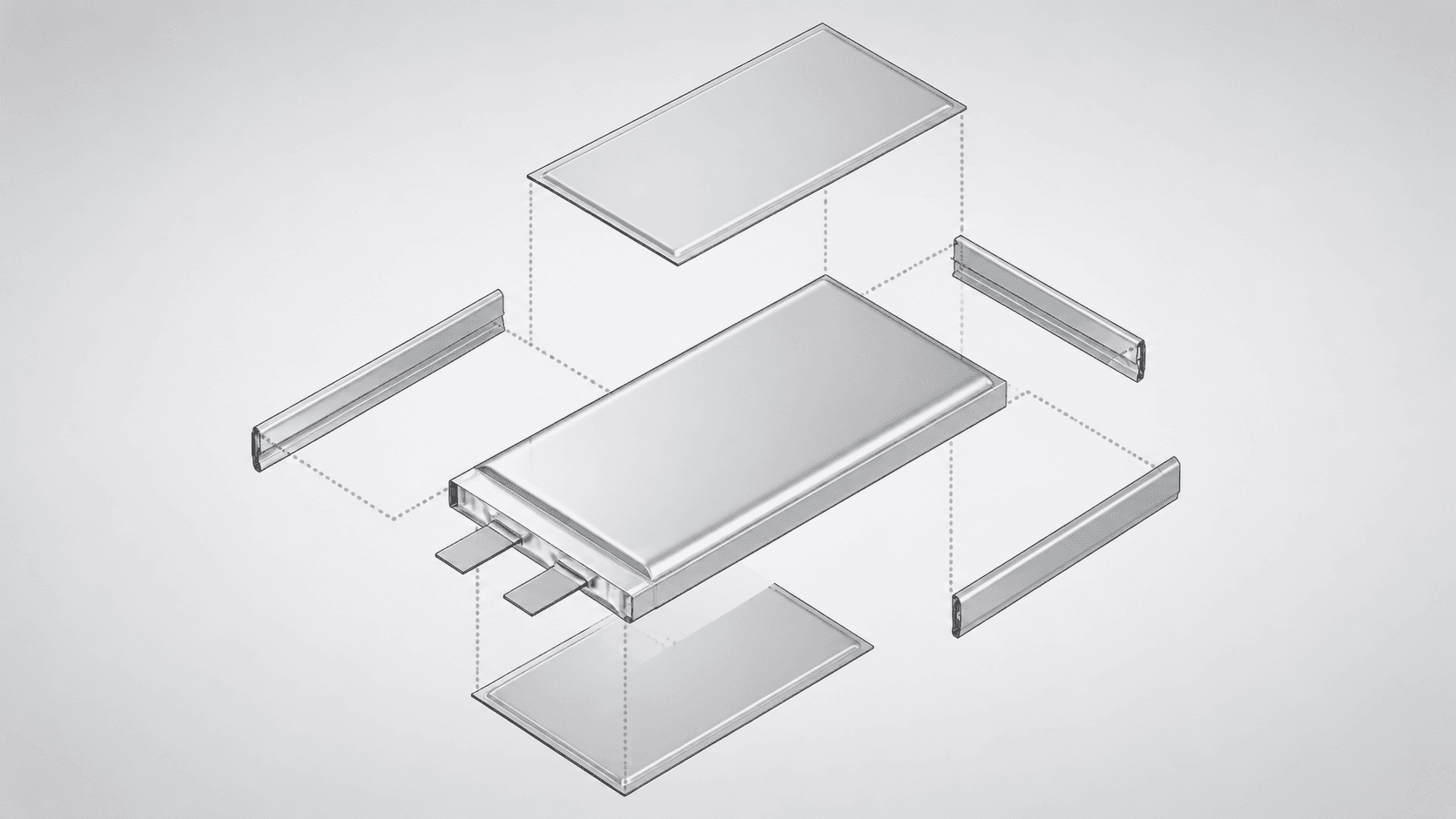
A complete pouch cell inspection station covers six surfaces: top face, bottom face, two long edges, and two short edges (which contain the positive and negative tabs). Most lines combine 4 to 8 cameras with multiple lighting geometries per camera. The right architecture depends on cell format, line speed, and where in the production sequence inspection happens (post-stacking, post-tab welding, post-pouch sealing, or end-of-line).
The hardest part is not detecting any single defect. It is doing so consistently across the foil's wide reflectance range without false rejecting on legitimate surface variation.
Surface defects on the foil
Scratches and gouges
Caused by handling damage during stacking, transfer, or robotic placement. Scratches that penetrate the foil's polymer-aluminum laminate are catastrophic; surface scratches in the polymer overcoat are cosmetic. Distinguishing the two requires sub-millimeter depth sensitivity. Detection approach: structured-light or photometric stereo combined with a CNN trained on per-class severity.
Dents and deformation
Caused by stack misalignment or mechanical contact during cell forming. Dents shallow enough to be invisible to a worker can compromise the foil-electrolyte barrier. Detection approach: depth-aware imaging plus baseline subtraction against a known-good cell silhouette.
Foil protrusions and bulges
Internal pressure or stack misalignment can produce visible bulges on the foil. These are catastrophic indicators (electrolyte gas evolution, separator failure) and must be caught with zero escapes. Detection approach: 3D profile measurement at multiple cell points, with conservative thresholds.
Pinholes and microperforations
Small punctures from handling or laminate manufacturing defects. Pinholes are the most common cause of slow-leak failures that emerge weeks after cell production. Detection approach: high-resolution imaging at 8 to 12 µm pixel size combined with dye-penetrant or backlight inspection where line architecture allows.
Tab and weld defects
Tab deformation and misalignment
Pouch cell tabs (positive and negative) are typically aluminum and copper foils ultrasonically welded to internal current collectors. Tab bending, twisting, or misalignment outside spec creates assembly issues downstream and can compromise contact integrity. Detection approach: edge-aware AI classifiers trained on geometric pose plus dimensional measurement.
Weld nugget defects
Ultrasonic weld nuggets must show consistent grain structure and no porosity. Surface inspection catches the visible failure modes: undersized nuggets, missing welds, incomplete fusion, surface contamination. Cross-section porosity requires other inspection modalities.
Tab burrs
Sharp metallic burrs on tab edges can puncture the separator under cell pressure, causing internal short circuits and thermal runaway. Detection approach: edge-tangent imaging at 5 to 10 µm pixel size, classifier trained specifically on burr geometry.
Seal defects
The pouch seal is the cell's primary barrier against electrolyte leakage and moisture ingress. Seal defects are the second-most common cause of field failures.
Incomplete seals
Heat-seal regions that did not reach full bond temperature show as visual color or texture differences from a complete seal. Detection approach: trained AI classifier on seal-region color and texture features.
Seal wrinkles and folds
Foil wrinkles in the seal region create leakage paths even when the seal is otherwise complete. Detection approach: depth and texture imaging combined with a wrinkle-specific classifier.
Seal contamination and electrolyte intrusion
Particulate or electrolyte presence in the seal zone indicates a contamination event upstream and a near-certain field failure. Detection approach: trained classifier on seal-zone foreign material with high recall priority.
Performance targets at gigafactory scale
The benchmark targets we see customers operating to:
- Cycle time: 2 to 3 seconds per cell at single inspection station, faster with parallel stations
- False reject rate: ≤5 percent across all defect classes
- Critical defect escape rate: 0 percent on foil protrusions, seal contamination, tab burrs
- Inspection coverage: 100 percent of cells, all six surfaces
- Pixel resolution: 8 to 12 µm/pixel for surface defects, 5 to 10 µm/pixel for tab burrs
Why the false reject rate matters more than the escape rate
Every gigafactory pouch cell program optimizes the same trade-off: catch every safety-critical defect (escapes near 0 percent) without rejecting healthy cells (false rejects under 5 percent). The economics are asymmetric. A safety escape can trigger an EV recall costing tens of millions of dollars. A 5 percent false reject rate on a 1-million-cell-per-day line discards 50,000 healthy cells daily, which at $80 per cell is $4 million per day in scrap.
The platforms that win in pouch cell inspection are the ones that hold both targets simultaneously. This usually requires a combination of: high-resolution imaging optimized per defect class, defect-class-specific decision thresholds, continuous learning to absorb production drift (see Haystack), and synthetic data generation for rare critical classes (see OV Auto-Defect Creator Studio).
Where to put the cameras
Three inspection points typically yield the best detection-rate-per-camera economics:
- Post-stacking inspection for foil surface defects before sealing locks them in.
- Post-tab-welding inspection for tab geometry, burrs, and weld surface quality.
- Post-sealing end-of-line inspection for seal integrity, electrolyte intrusion, and final dimensional checks.
Skipping the post-stacking station is the most common false economy. Surface defects sealed inside the pouch are not recoverable, and end-of-line inspection cannot reliably detect interior foil damage.
Getting started
For more on AI inspection at gigafactory scale, see our overview of gigafactory battery cell inspection and the specific challenges of scaling cell production.
Inspecting pouch cells at gigafactory scale?
Send us your hardest defect class. We will train and deploy a model on your actual cell images in 1 to 3 hours and benchmark detection rate against your current inspection process.
Request a Pouch Cell PilotSee how Overview AI inspects pouch cell defects
Send us a photo of your part or defect and a vision engineer will tell you whether Overview can catch it, with most systems deployed on the line in days.
Related Articles
AI Inspection for Gigafactory Battery Cell Production
How AI vision inspects battery cells at gigafactory scale to prevent escapes and recalls.
Read More →3 Quality Inspection Challenges in Battery Gigafactories (and Fixes)
The three quality inspection challenges gigafactories face and how AI vision addresses them.
Read More →Ghost Defects in Battery Welds: How Edge AI Makes the Invisible Visible
Detecting micron-scale weld misalignments on reflective battery caps with edge AI.
Read More →